During the pandemic (2020,2021) I was really bored. And I wanted a fader bank to control parts of my DAW. These tend to be expensive, so I decided to make my own and learn some new skills in the process.
GitHub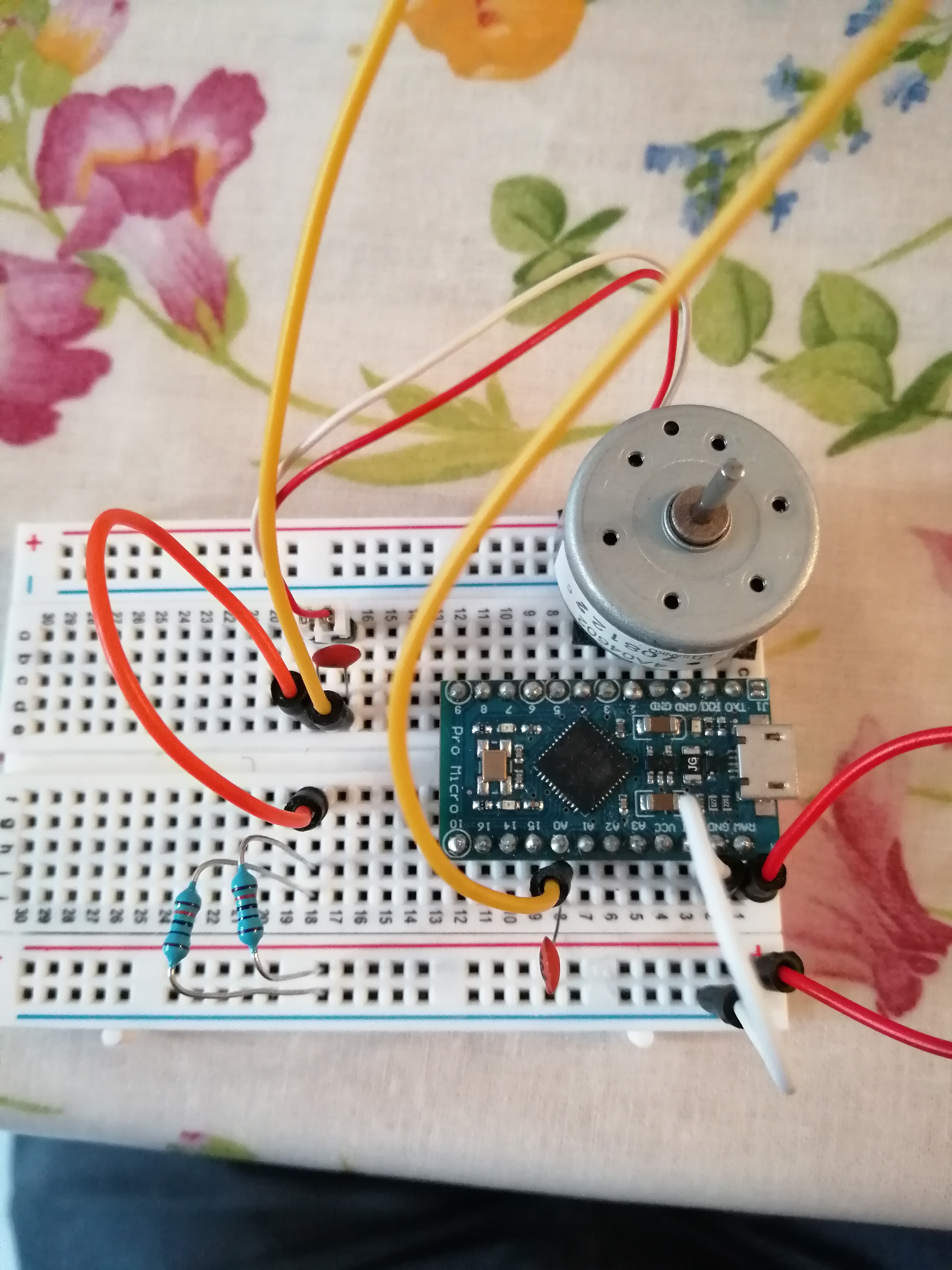

Project Requirements#
I started with laying out what I wanted from the project:
- A set of faders that could control the faders of my DAW
- A set of programmable buttons
- A smooth scrolling wheel for scrubbing the timeline of my DAW
- All powered over USB (no external power needed)
- No third party software needed (plug and play)
- Works with multiple DAWs
- Multi platform (I use both a PC and Mac)
I decided to make use MIDI to communicate with the DAW as that seemed the most universal between DAWs.
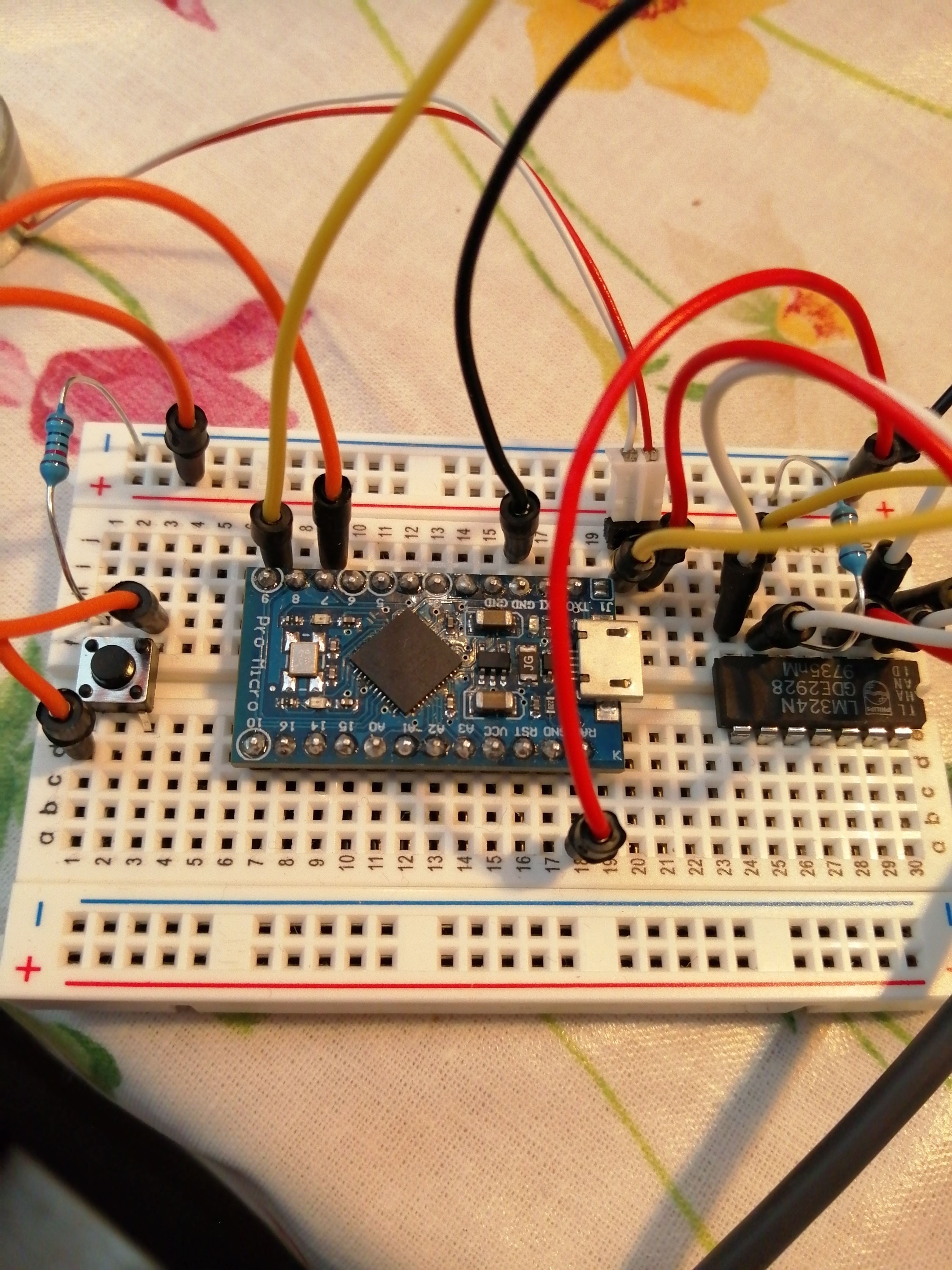
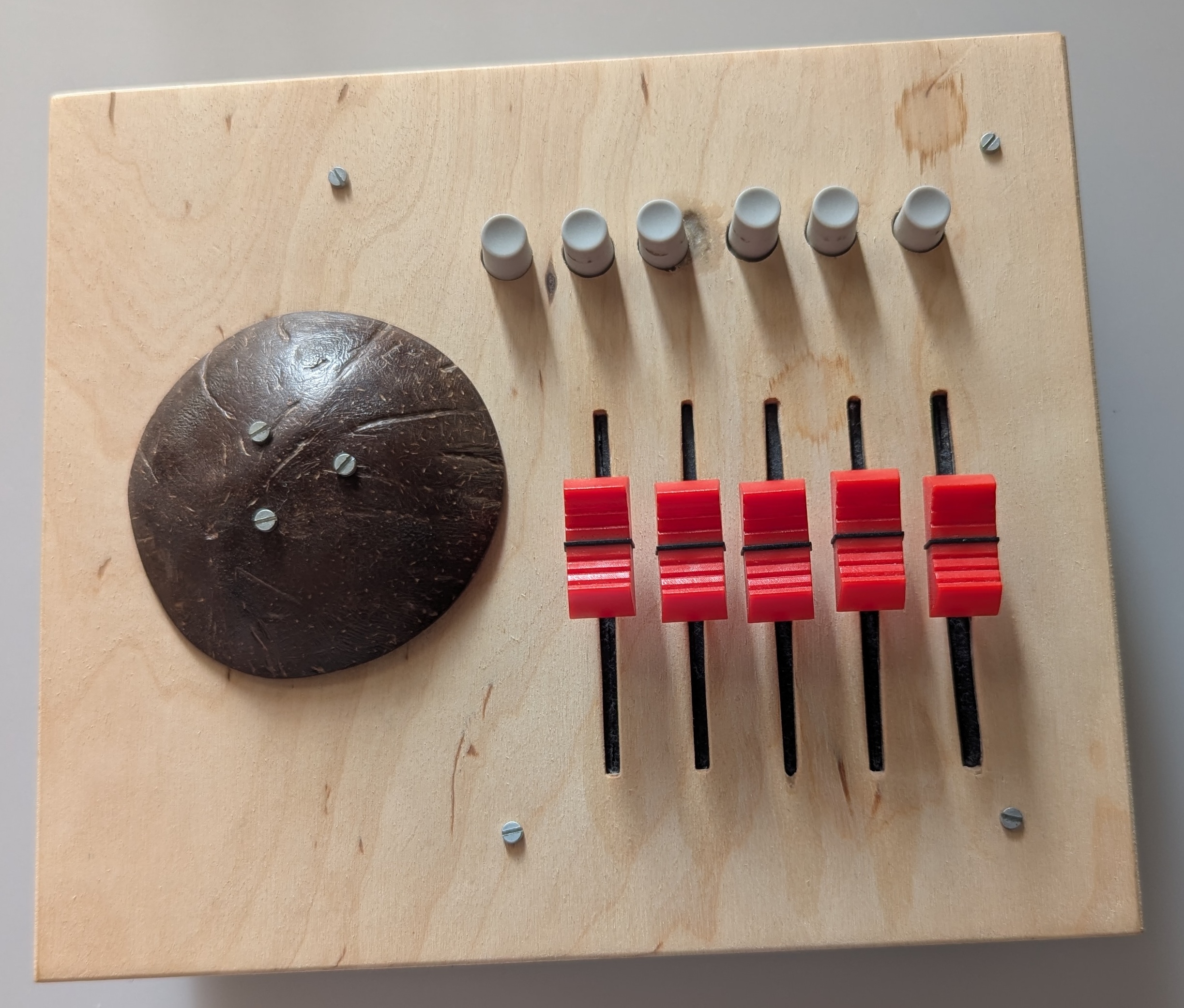
After some research I settled on using an Arduino Leonardo (because it had enough data inputs) and settled with 6 buttons, 5 faders and the wheel.
Buttons/Faders#
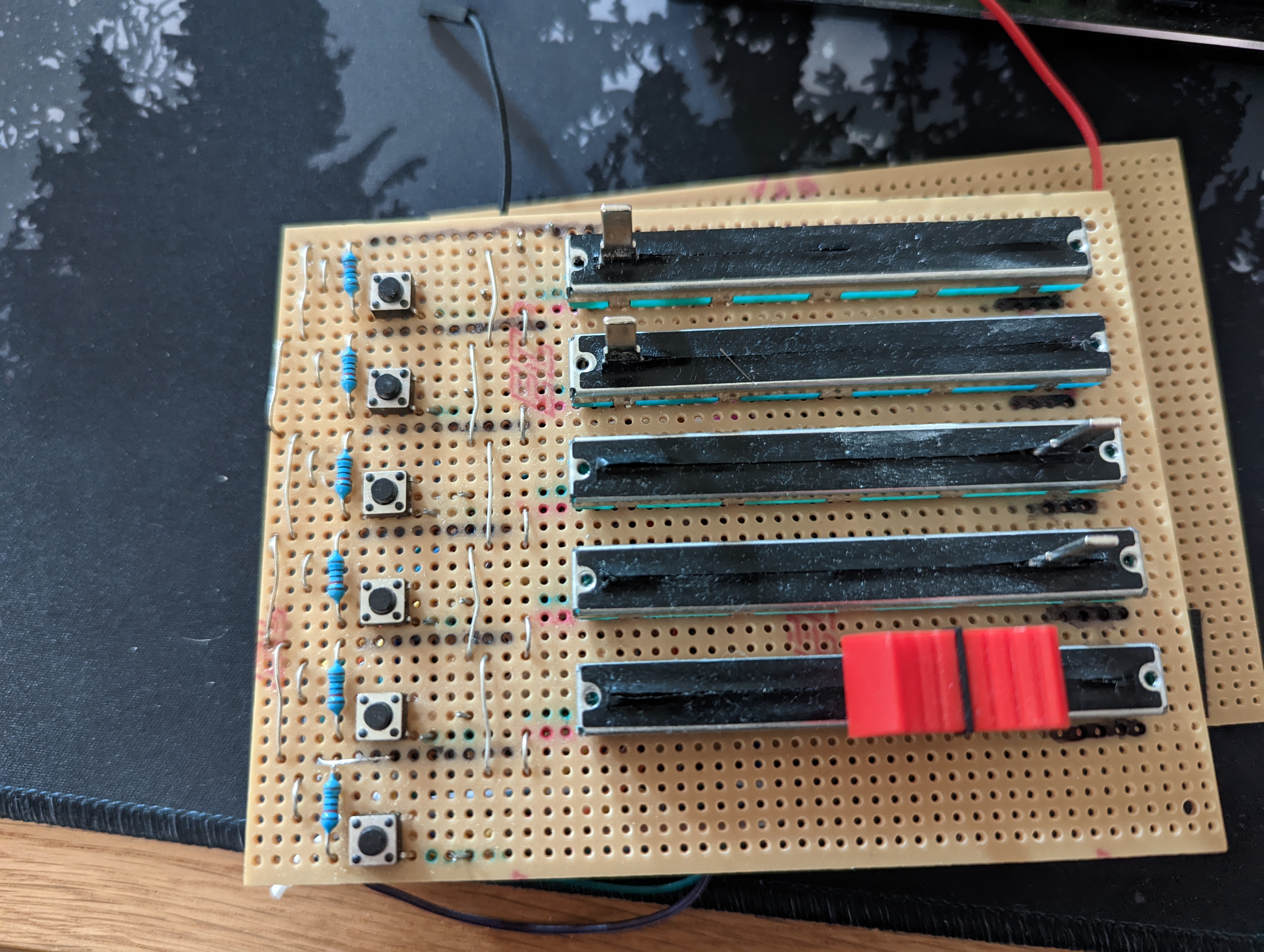
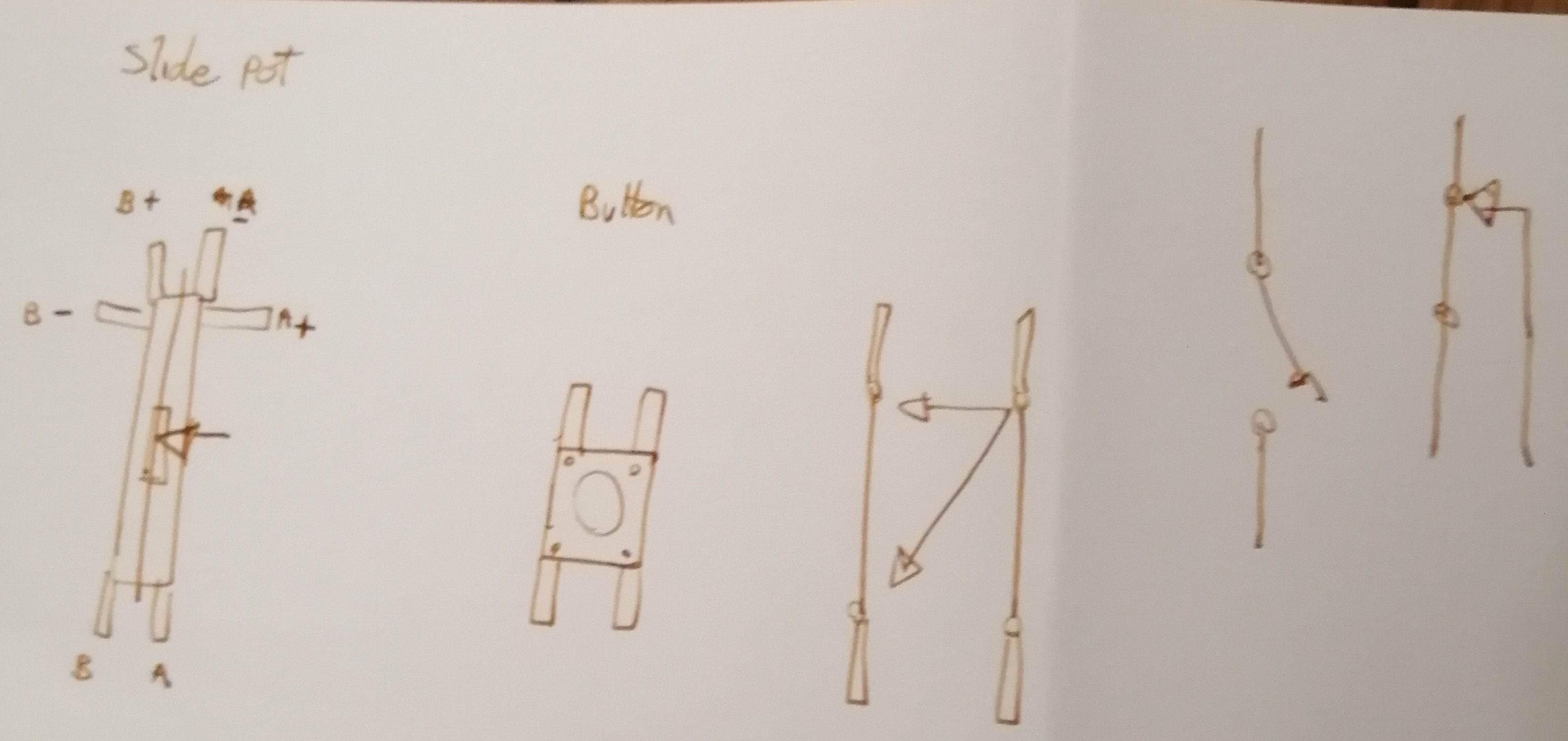
The faders and buttons were easily the simplest part of the project. A button has a simple On and Off state, which is really easy to read on the data inputs of the Arduino.
A fader is slightly more complicated. I used a sliding potentiometer, linked it up to a power rail, and read the output voltage through the data input. Using the classic formula of Voltage = Current * Resistance, as the resistance of the pot increased, so would the voltage, so it becomes a simple matter of mapping the read voltage to a MIDI value. MIDI controls can only go between 0 and 127 numerical values which means you can have a maximum of 128 steps to map the voltage to.
Encoding Wheel#
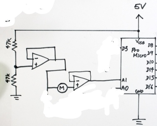
I based my design of the encoding wheel off of Evan Kale’s design in this video, using the voltage read out from spinning a CD drive motor. The idea behind this was that it would be a nice free spinning wheel, with high precision, instead of a segmented wheel like most mouse scroll wheels are. Spinning the motor one direction gives a positive voltage read out, and spinning it the opposite gives it a negative voltage. The issue I ended up running into with this approach, as opposed to just using a rotary encoder, was that it was too precise, and ended up needing a lot of normalization and filtering to make it less sensitive. The other issue was that I mapped it to MIDI. In hindsight it would have made or sense to treat it like a mouse wheel, because remember MIDI can only have 128 unique values. This is fine for a fader or button or key press which have very limited travel. But if you’re trying to have a free scrolling wheel, you’ll run into the max 128 steps very quickly. This made scrolling a long timeline perform large leaps, rather than a smooth scroll. Essentially the longer the timeline, the less accurate the scroll wheel.
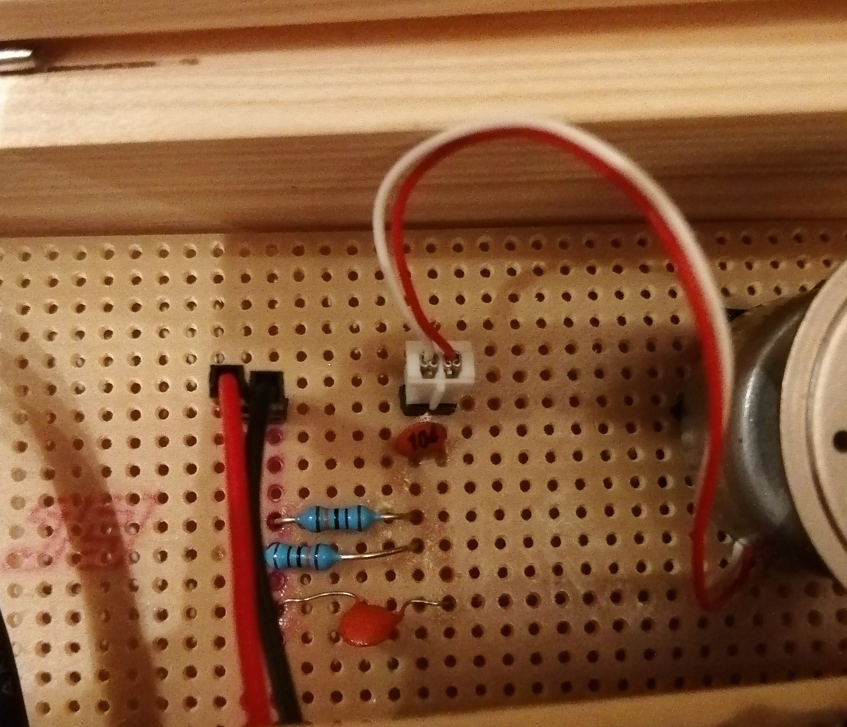
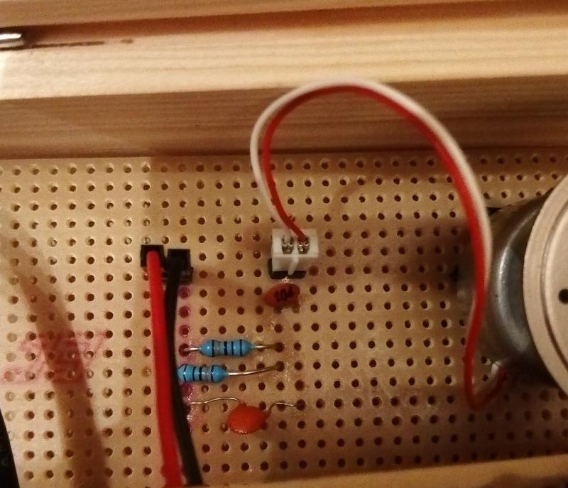
For normalizing the motor voltage I initially tried using an Op-Amp, but that was really complicated, and I ended up settling for a much simpler filtering circuit using capacitors.
The Circuit#
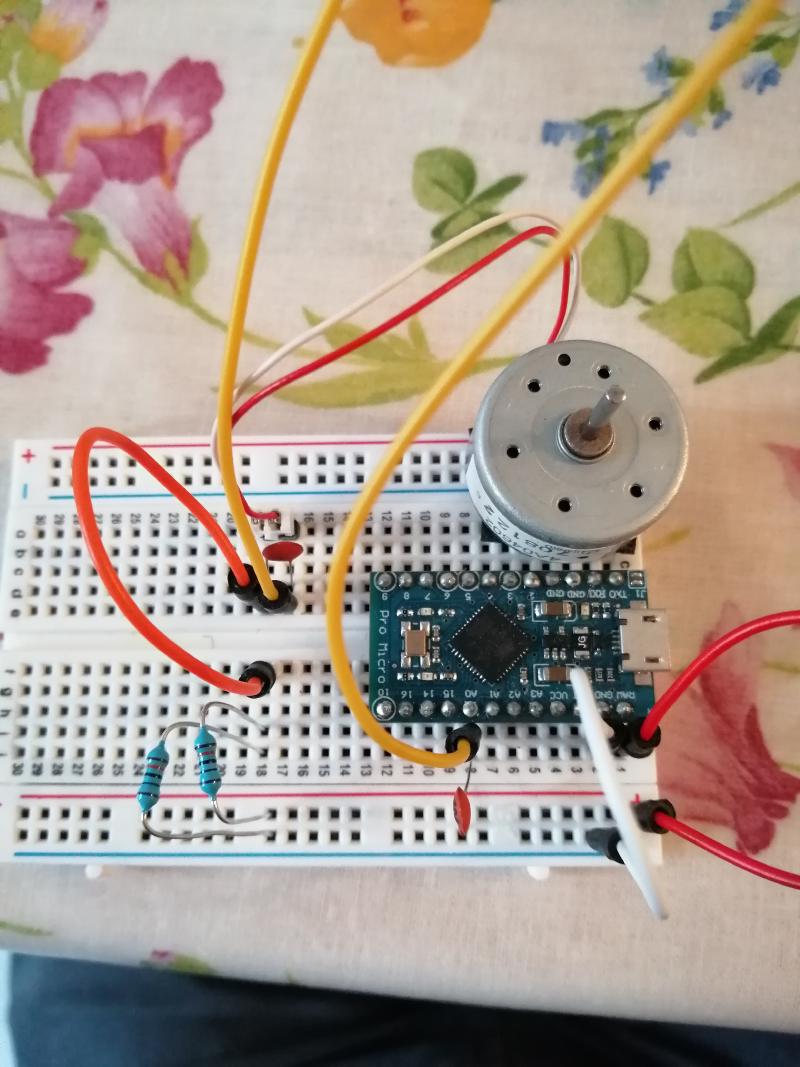
After considerable experimentation with a bread board and a rats nest of wires it came time to solder a proper circuit board.
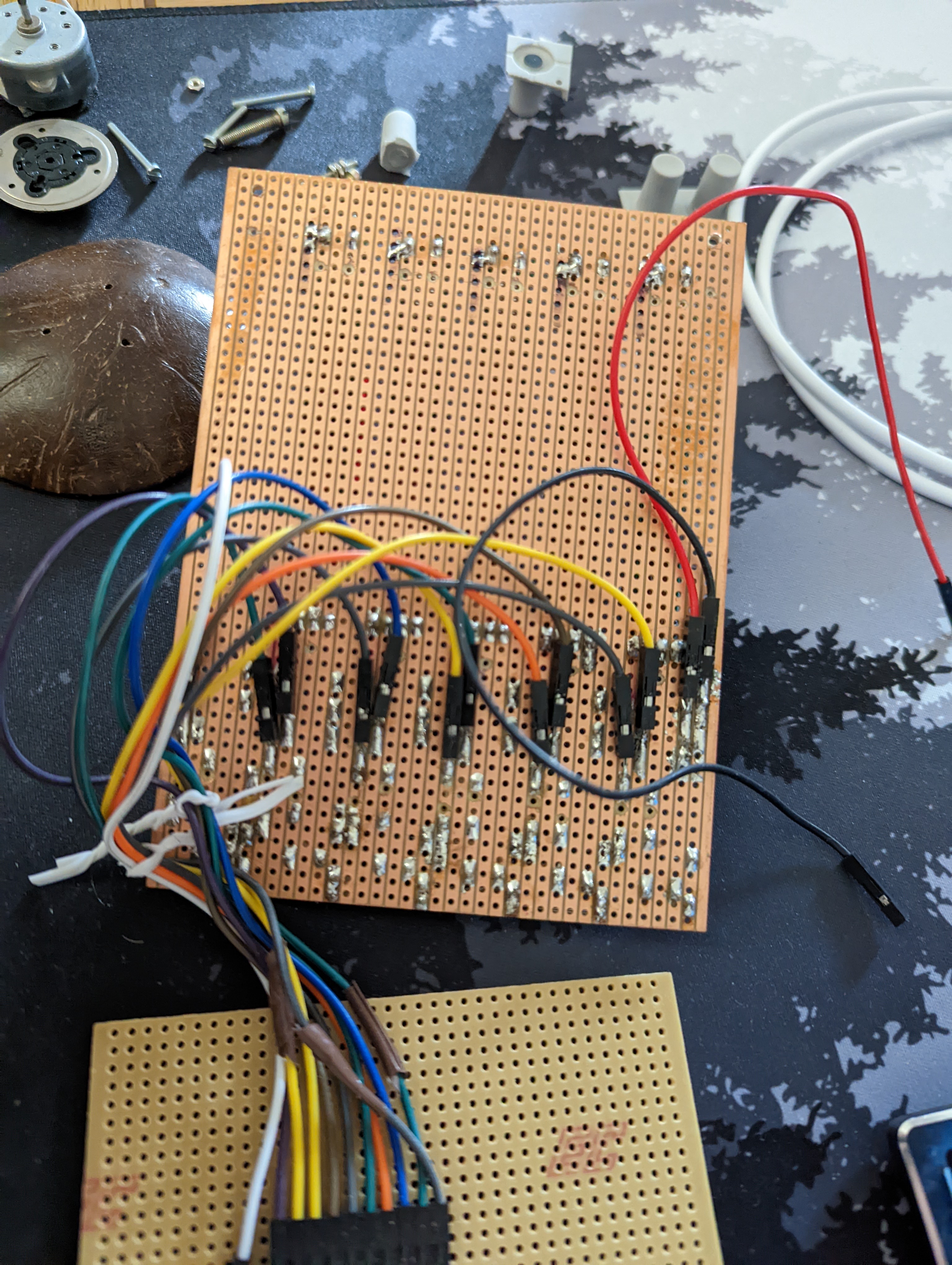
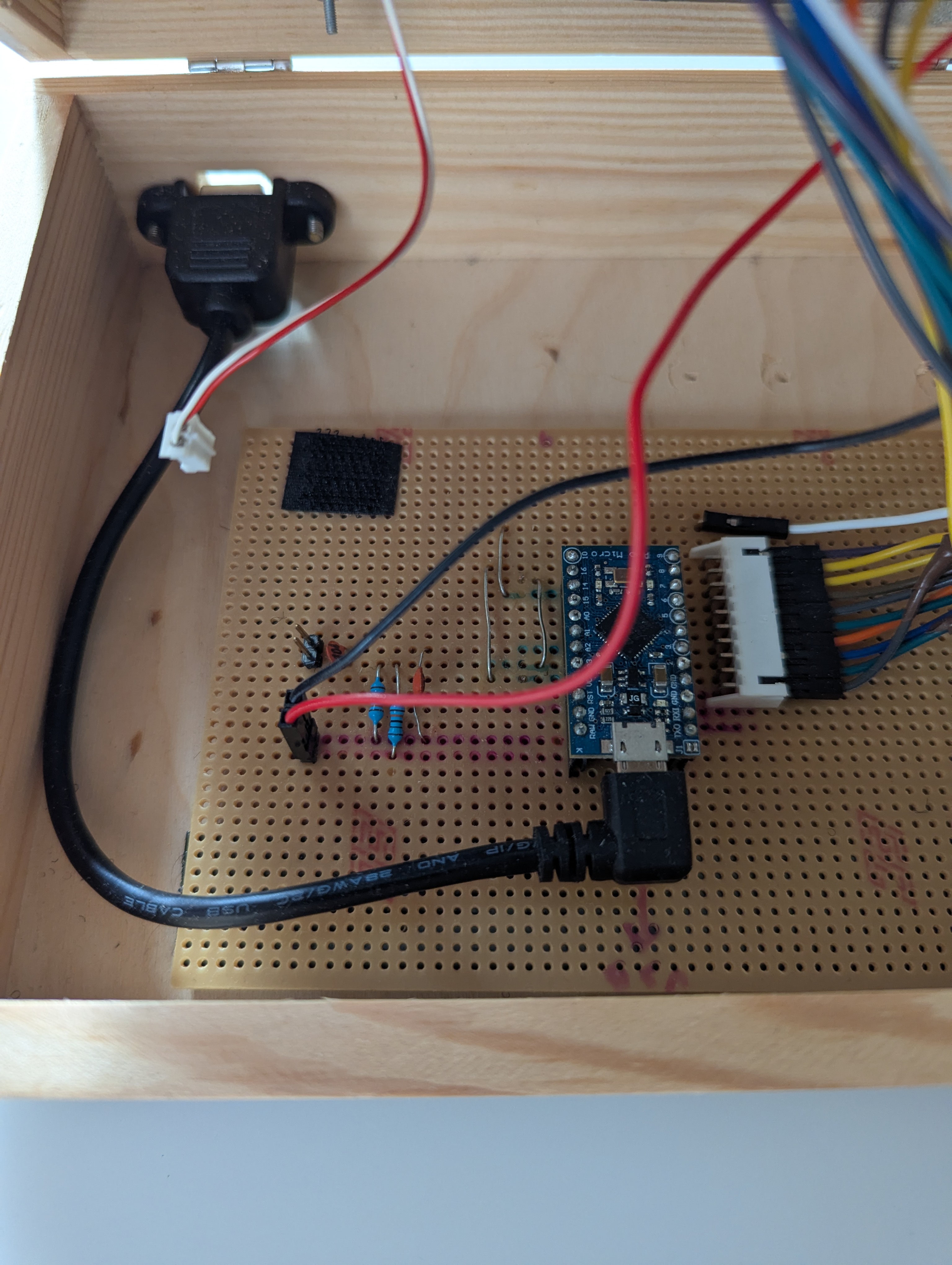
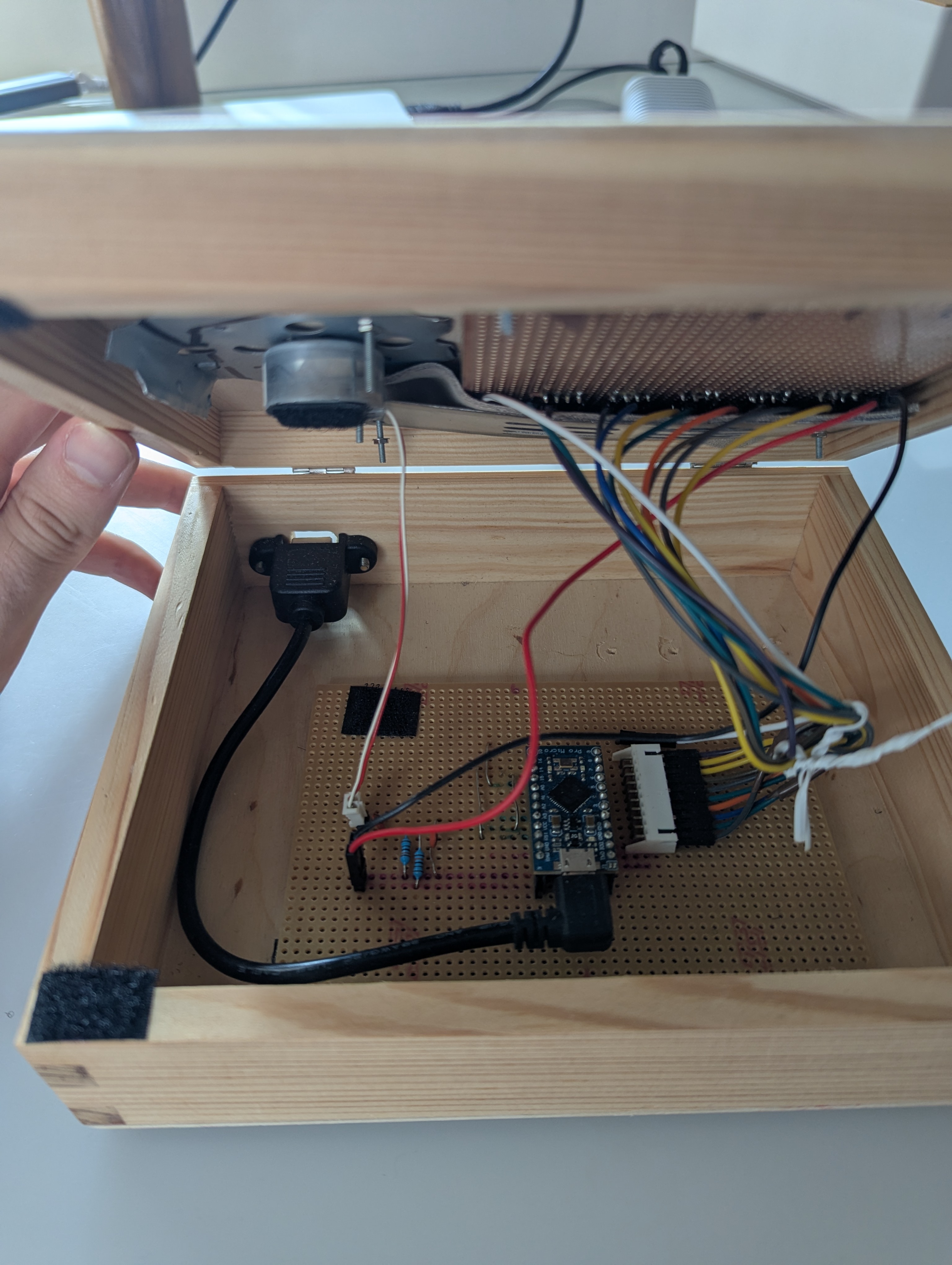
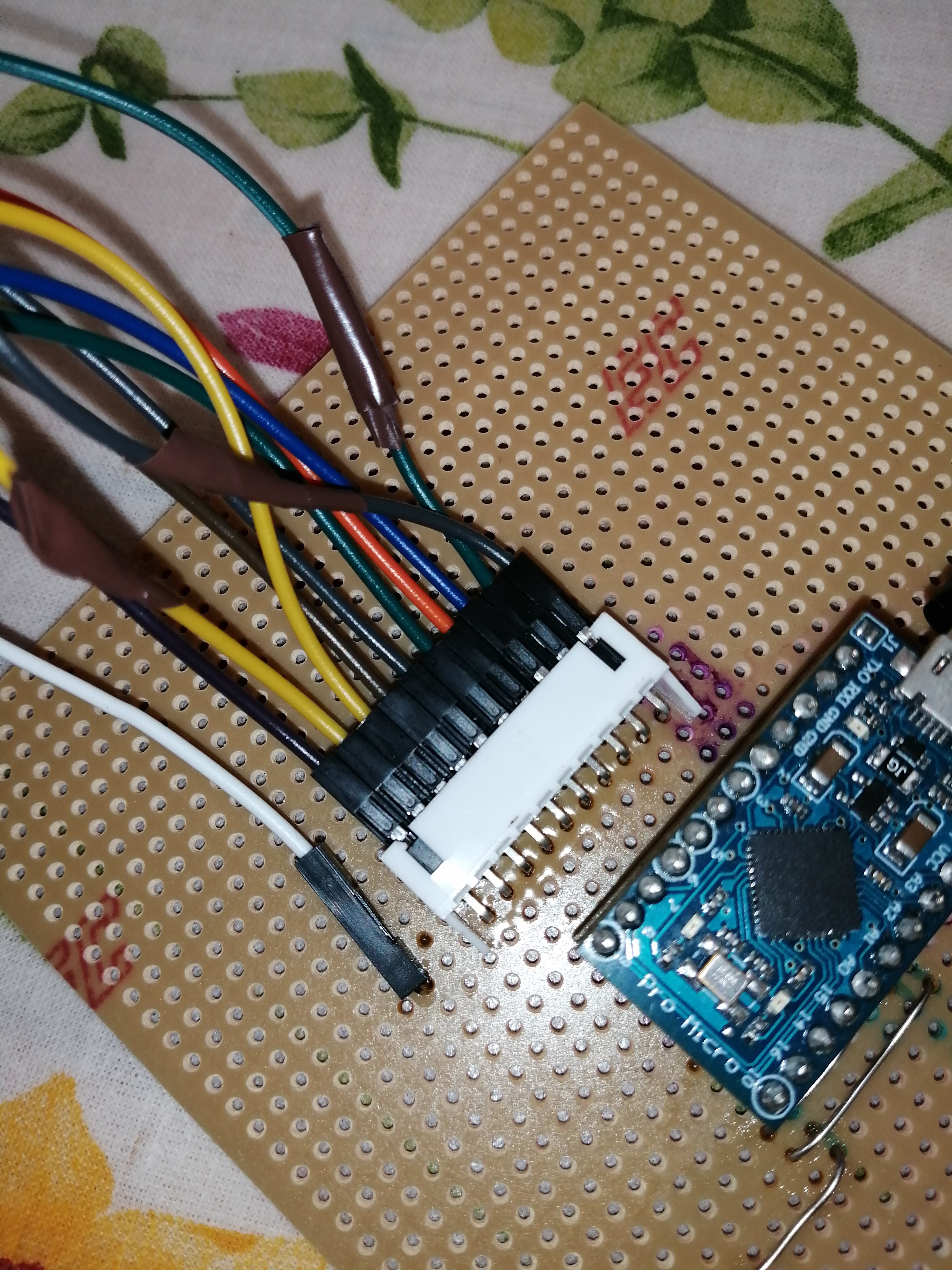
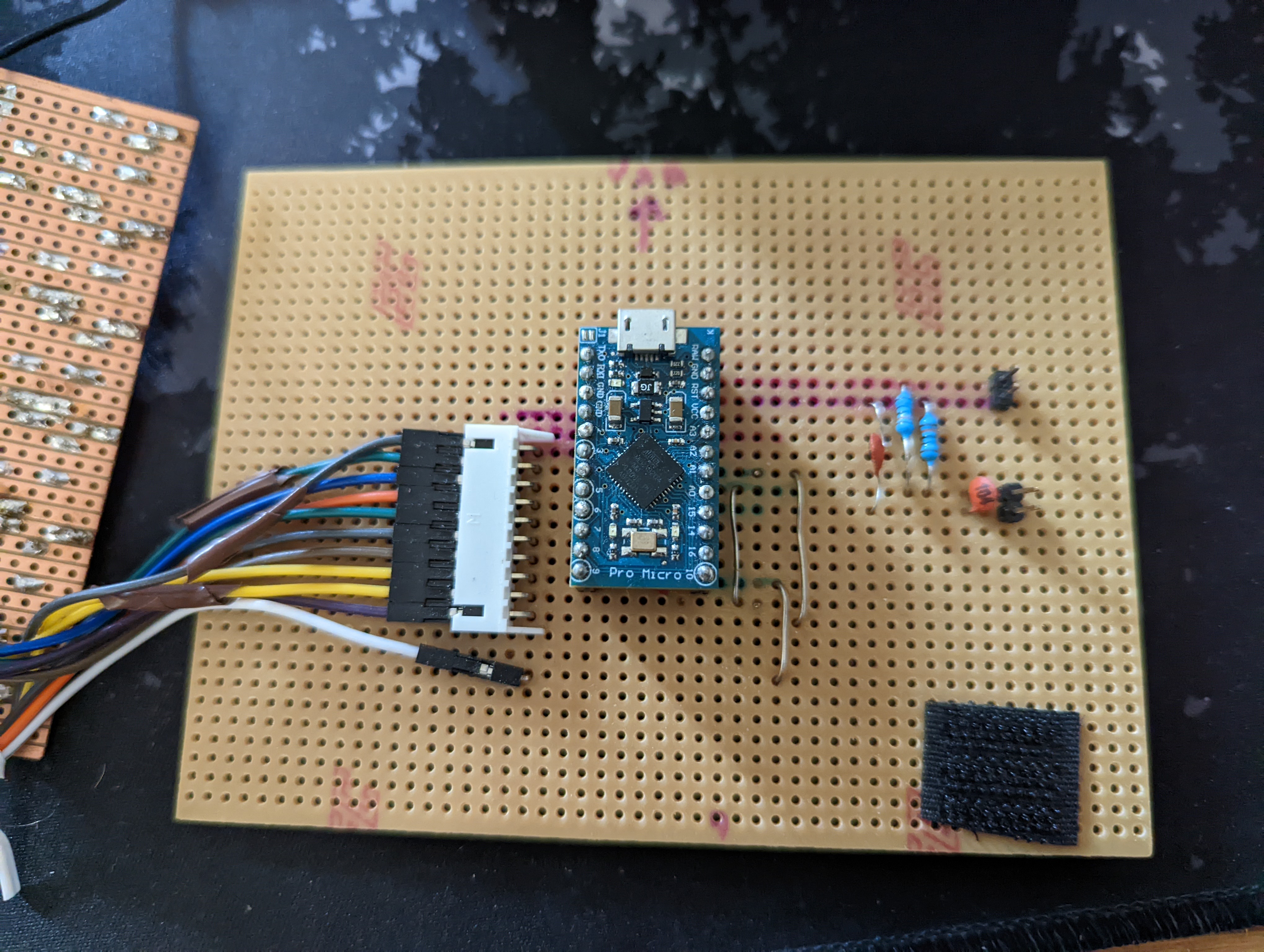
Project board follows the same logic as a bread board, but involves cutting traces and soldering components to it to create your circuit. After several dry runs to figure out the best layout for it, the final result consisted of a main board featuring the Arduino, and filtering circuit, and a daughter board, connected by a series of wires to the main board, holding the faders and buttons.
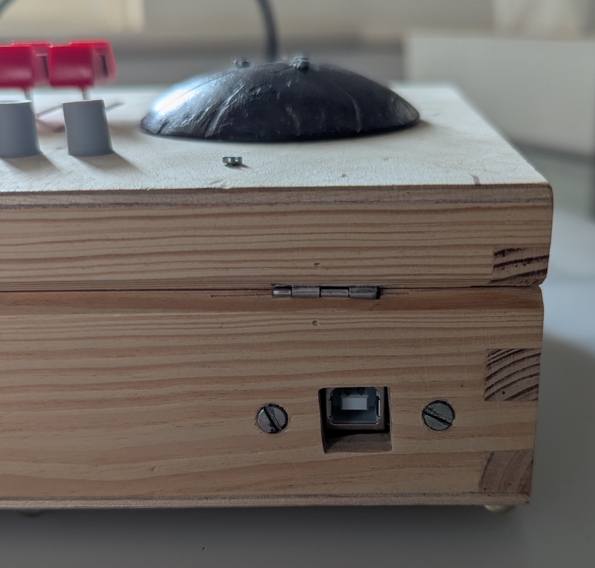
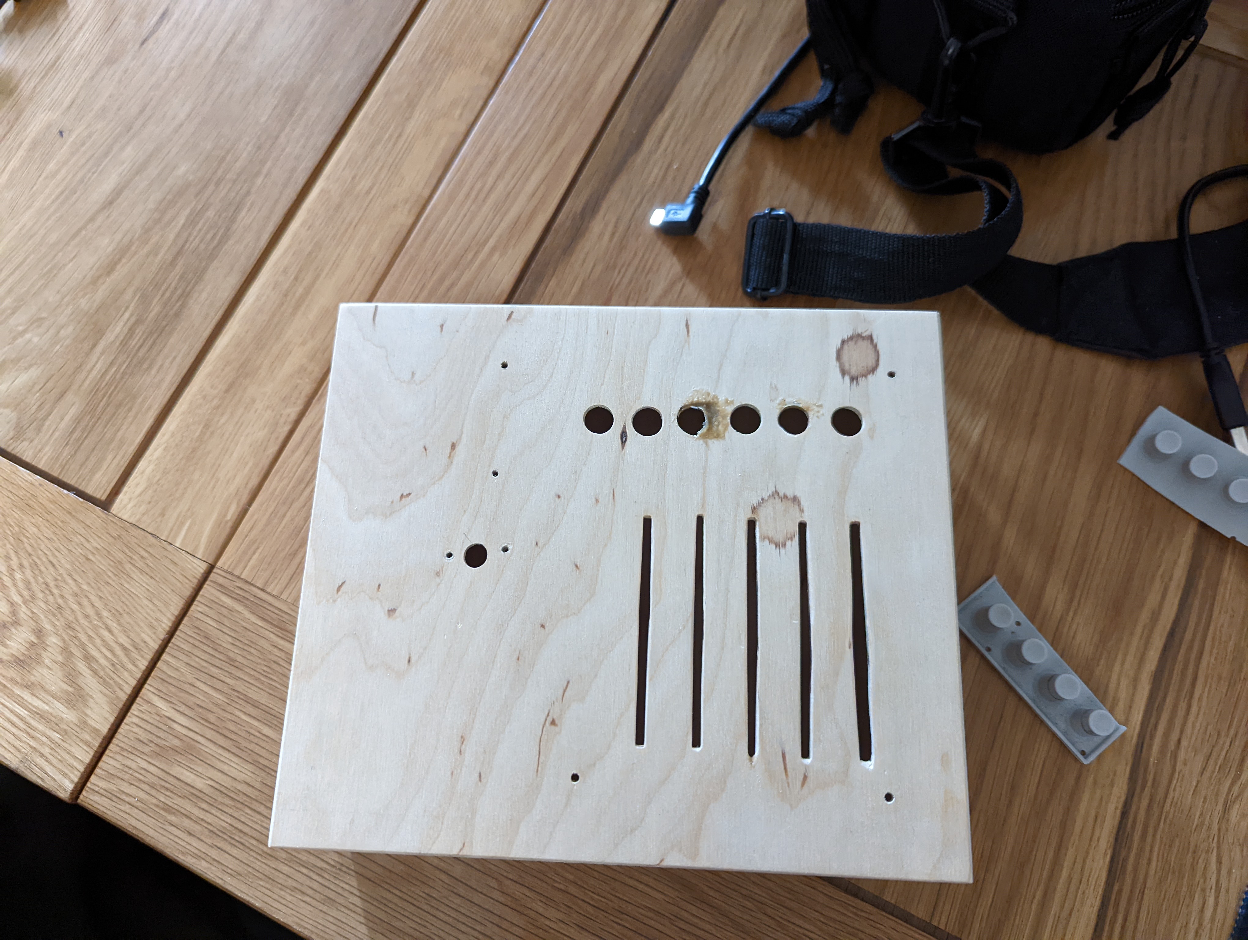
This was all mounted in a wooden box with holes cut in it, securely held with screws and velcro so that it was all accessible for repairs/tweaking. The input of the Arduino is accessible through a USB B - USB MicroB adapter routed to the externals of the enclosure.
The firmware code was all written in C++, and can be found on my GitHub page.
Things I would do differently now#
Improve the enclosure. The final encasement ended up being a bit janky, as I lacked tools to cut proper holes in it, and it sits quite high off of a work surface making the ergonomics quite difficult to work with. If I were to make it over again, I would go for a more bespoke project box or case, perhaps a 3D printed one. This would allow me to have a more robust mounting system for the project boards, featuring stand-offs and proper machine screws.
Improve the encode wheel. I would also use a rotary encoder or magnetic encoder instead of a CD motor. While it was an interesting experiment, it ultimately had quite a lot of headaches that could be avoided with a proper encoder. I would also look into programming it as a human interface device (HID) or something of that nature, and not tie it directly to MIDI because of the lack of accuracy with larger timelines.
Make it USB C. This one was an oversight on my end, and any for thought would have realized that USB C is much more user friendly than the USB B adapter I did use.
Use AI to help with the firmware I made this project before the advent of LLMs in our everyday life, and while I’m not a fan of how they’re used in the creative spaces, they’re brilliant for helping with code, and would have made the project considerably easier. But then again would I have learnt as much? Probably not…
Reply by Email